Hello, we have purchased your water controller, there are integrated controller and separated controller, please provide the wiring diagram, and the system structure diagram, thank you!
Hello, thank you for purchasing our company’s smart card swipe water controller, you can refer to the following pictures:
Wiring diagram of integrated water controller:

The four-core wire of the water controller, the gray wire is connected to RS485 A, the blue wire is connected to RS485 B, and then RS485 is plugged into the computer, the water controller is managed by consumer software in the computer, and then the red and black wires are connected to the positive and negative poles of the 12V DC power supply respectively. After the line is connected, plug the power adapter into 220V city power to supply power to the device.
System structure diagram of integrated water controller:

Note: You need to pay attention to the A line and the B line when connecting, please do not connect it wrongly, the wrong connection will cause the entire system to fail to communicate normally.
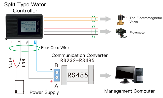
Wiring diagram of separated water controller:

The four-core wire of the water controller, the gray wire is connected to RS485 A, the blue wire is connected to RS485 B, and then RS485 is plugged into the computer, manage the water controller through consumer software in the computer. Connect the red wire and black wire to the positive and negative poles of the 12V DC power supply, respectively. The two-core wire and the three-core wire are respectively connected to the solenoid valve and the flow meter. After the line is connected, plug the power adapter into 220V city power to supply power to the device.
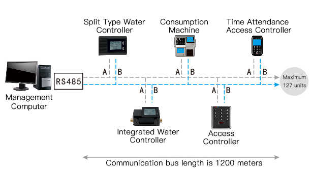
Structure diagram of separated water controller system:

Note: Please pay attention to the A line and B line when connecting, please do not connect wrongly, the wrong connection will cause the whole system to fail to communicate normally.
If you still don’t understand, you can ask us at any time, we will answer you in time and give you guidance.

